
PID Tuning Objectives and Considerations
The primary objective of tuning a PID controller is to optimize and stabilize the controller’s response, thereby minimizing the error between a process variable and a setpoint value. The tuning of a PID controller should enable the controller to react to setpoint changes and unmeasured disturbances while minimizing the variability of the process variable.
Secondary objectives often exist and may need to be considered when tuning a PID controller. For example, level controllers, such as holding a tank at 50% capacity, may not need to be tuned as aggressively to hold the level exactly at a setpoint. If the tank is installed to serve the purpose of a buffer in mass flow management between two process units, the purpose of the controller may be to not allow overflow or emptying of the tank while keeping the tank outflow as steady as possible and keeping the level within reasonable bounds around the target capacity.
When the actuator is a transformer or a control valve, tuning that ensures reasonable travel of the actuator may be desired to protect the actuator from additional wear, allowing it to last its maximum lifetime.
These tuning objectives are often conflicting, and engineers face an optimization problem as they balance the importance of the control objectives relative to economic factors. If a certain amount of PV deviation from the setpoint causes significantly increased cost to the manufacturer due to scrapped and downgraded product, this cost typically far outweighs the wear and tear of the actuators. To solve this optimization problem, the solution would be to tune the PID controller aggressively in order to minimize PV variability around the setpoint, even though it causes the actuator to work harder, possibly requiring more frequent maintenance or replacements. This prioritizes the control objective of stabilizing the PV over the increased wear of the actuator.
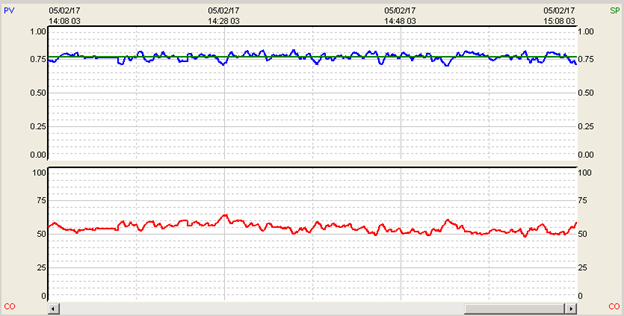
Figure 1: The aggressive tuning of the above process holds the process variable at setpoint with minimal variation above noise levels. Note that the valve has to move aggressively to achieve this result.
If higher PV variability around setpoint can be tolerated, in the sense that it does not increase the cost of operation, then tuning can be slowed down to protect the actuator, so more conservative PID tuning can be applied. Such a situation may occur in tuning cooling air or cooling water circuits when cooling media temperatures are well within operating ranges and aggressive control to an exact cooling water temperature does not provide additional value.
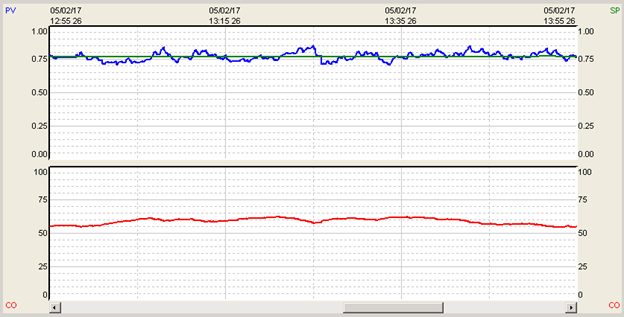
Figure 2: Tuned more conservatively, the same process does not hold the process variable to the setpoint as well, and there is more variability in the product from the desired setpoint. This will likely affect the quality and/or cost of the product. Note that the valve movement is much smoother with this tuning and will likely result in less maintenance cost and less wear on the process hardware.
A combination of conservative and aggressive tuning may be applied during the previously mentioned level control example. To stabilize the flow out of the tank, conservative tuning can be applied when the tank level is in the predefined range. When a condition or disturbance occurs that causes the tank to experience higher or lower than usual inflow, the mass balance must be satisfied, and an aggressive control action should be applied to prevent tank overflow or emptying. In such a case, the objective of stable outflow is sacrificed to prevent violating tank level limits.
During a process unit’s first startup, engineers typically apply a set of initial tuning parameters. These parameters may be copied over from similar units previously commissioned or set to default parameters provided by the DCS/PLC vendor. Often, the starting PID parameters will be set to slow and conservative parameters to avoid initial instability, or parameters favoring Integral action to provide for smooth controller output. The goal of the initial PID tuning parameters is to provide for some level of safe operation of the process unit to get the unit started. Later, throughout commissioning, the PID controllers are properly tuned to stabilize the PV and minimize the error between the PV and setpoint, while accounting for any additional control objectives.
If tuning software or a specific tuning method is used, when tuning multiple PID parameters, a pattern of tuning can be observed. However, if utilizing a trial-and-error method, then the user’s subjective preferences play a significant role.
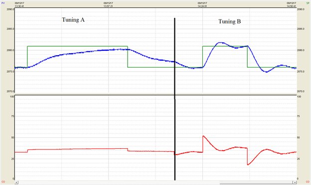
Figure 3: PID controller response for two different sets of PID tuning parameters. Tuning A is slow and takes a while to reach the setpoint. Tuning B reaches setpoint relatively quickly but has some resultant overshoot in the process variable. If the process cannot tolerate overshoot from the setpoint by more than 1-2 EU, then tuning A would be the desired tuning. This would reduce the chance that the product is scrapped when the SP is exceeded. If overshoot in the process can be tolerated, tuning B would be more desirable. Since the setpoint is reached sooner, more products can be produced over time.
Engineers on the process side tend to favor the process objectives more, such as tuning a PID controller to hold PVs closely to the setpoints, favoring proportional action. Whereas engineers responsible for the automation infrastructure may prioritize protecting the infrastructure and thus will tune more conservatively, favoring the integral action. It is not uncommon for engineers to differ in the prioritization of their tuning objectives.
Tuning based on subjective preferences should be avoided, even though it may provide for stable and robust operation of the PID controllers. PID controllers make important decisions on control outputs every second, and if these decisions are not optimal concerning the actual cost of manufacturing, the tuning will yield sub-optimal overall plant results.
Extremely slowly tuned PID controllers can be considered to virtually be operating in manual mode; they will not move the control output much, even though frequent or permanent disturbances are present.
Extremely aggressively tuned PID controllers may be operating very close to instability; they will reject disturbances very aggressively, holding the PV at setpoint very tightly, often experiencing low magnitude constant oscillation around the setpoint that may be difficult to notice, e.g. due to measurement noise. If a setpoint change is made or operating conditions change even slightly, an aggressively tuned controller may start to oscillate dramatically or even saturate at maximum and minimum control output repeatedly.
PID control tuning is an engineering task where operational and economic objectives should be weighed, and analytical methods should be used to determine a viable range of P and I settings. The robustness of performance should be verified over time after the tuning was last changed. This approach will yield close-to-optimal tuning based on operational objectives and ensure safe operation at minimal production cost.
For more helpful information on how to tune PID controllers, request a free copy of our PID Loop Tuning Pocket Guide.
Or to gain hands-on experience, consider our PID Controller Tuning Training.

