Tuning Cascade Loops
The use of a cascade loop is a common strategy used to control systems that exhibit both fast-acting and slow-acting disturbances. Standard PID control can be tuned for typically slower acting disturbances, but the fast-acting disturbance cannot be addressed with a single PID. Utilizing a Cascade configuration allows the control to better handle both fast acting and slow acting disturbances.
One of the most common questions we get asked is, “I have a cascade loop; how do I tune it?” Typically, it is not the tuning of the PID loop that is an issue as much as it is a lack of understanding of how the cascade structure is designed to control a loop. The tuning of a cascade loop is quite simple once you understand the basic concepts. To illustrate the basics, let’s look at a common cascade loop application.
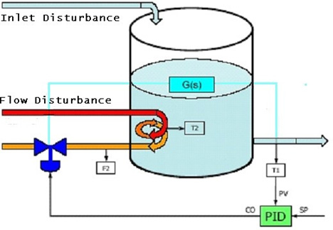
Figure 1 shows a tank that is heated via a steam valve. The goal is to control the outlet temperature [T1] via the steam valve. We can attach a standard PID controller to this loop to control the temperature as shown.
Figure 1. Standard PID Control of Tank Outlet Temperature
Handling Disturbances
Two of the many types of disturbances that can affect this process are:
- Inlet Disturbances – Fluctuations in the infeed flow or infeed temperature can cause disturbances to T1.
- Supply Flow Disturbances – Fluctuations in the steam supply pressure cause flow to fluctuate and thereby cause a disturbance to T1. The PID can only be tuned as fast as the process will allow. There is a significant amount of time (both deadtime and lag time) in the process.
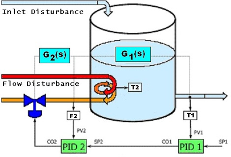
In this process, the changes in steam pressure cause the steam flow to fluctuate, and the controller will not detect such pressure variation until it affects the temperature. The overall process is very slow. A common way to resolve this problem is to use a cascaded PID configuration as shown in Figure 2.
Figure 2. Cascaded PID Control of Tank Outlet Temperature
PID 1 can be referred to as the Primary or Outer Loop. PID 2 can be referred to as the Secondary or Inner Loop. Essentially, what we did was to take our process response and split it into two pieces – a fast piece [G2(s)] and a slower piece [G1(s)].
- Note that we still only have one control Instead of manipulating the steam valve directly for temperature control, the valve is now controlling the flow of the steam to the process from PID 2.
- The temperature controller (PID 1) now determines the desired amount (the setpoint) of flow to control the temperature.
Cascade Control Considerations
- The inner loop (PID 2) must be faster than the outer loop (PID 1) for cascade to be of benefit.
If the inner loop is not faster than the outer loop, then the cascade will not offer any significant improvement in the process. - PID 2 can be tuned relatively fast and can respond to flow disturbances.
- PID 2 will minimize any fluctuation disturbances in the steam supply.
- PID 1 still controls temperature, and is tuned relative to the temperature process, which is slower than the flow process.
- Any disturbances within the inner (fast) loop can be corrected (by PID 2) without waiting for the disturbance to show up in the temperature loop (PID 1) for better (tighter and faster) temperature control.
- Tune two PIDs instead of the one PID as in our original configuration.
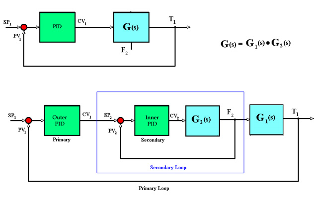
Figure 3. Outline of PID Control compared to Cascaded PID Control
Cascade Configuration Considerations
- In looking at Figure 3 we notice that the CO output of PID 1 is fed directly into the setpoint of PID PID 1 is dependent on PID 2 being in control to control the temperature.
- In our control logic, we should ensure that PID 1 is in track mode if PID 2 is in manual control.
- Also, when PID 2 saturates, it is important to inhibit PID 1 (that is, to stop PID 1 from increasing or decreasing). If PID 1 is not inhibited, controller windup will occur. Therefore, it requires proper engineering to implement cascade control correctly.
- Some controller manufacturers have a Cascade PID block that is designed to handle the coordination logic required to run the cascade correctly.
Summary
The simple answer to our question “I have a cascade loop; how do I tune it?” is:
- Tune PID 2 before tuning PID 1. Often, a simple proportional plus integral (PI) control is sufficient.
- PID 2 needs to be in control (typically AUTO mode) when tuning PID 1.
For additional assistance with cascade tuning, consider using the One-Shot Cascade tuning feature in INTUNE PID Tuning Tools, available from ControlSoft, Inc.
[This technical note was first published in 2007 and has been revised for comprehensiveness.]
Need more help tuning cascade loops? Contact us for additional guidance.


