
Methods for implementing Bumpless Transfer are widely used in process automation systems. However the concepts and the rationale behind the methods are many times a mystery to process operators and automation engineers alike. Let’s explore this subject in greater detail to unveil the underlying issues and gain better system awareness and insights.
What is Bumpless Transfer?
What is Bumpless Transfer (BT) and why do controllers need it? Our definition is as follows:
Bumpless Transfer is the method by which a controller can be transitioned from Manual mode to Automatic mode without disrupting the process.
Why do plant operators place control loops in Manual mode in the first place? There are many reasons why plant operators place control loops in Manual mode: following procedures for plant start-up, troubleshooting valve problems and improper tuning of controllers are the most common. When the plant operator decides to transfer a control loop from Manual mode to Automatic mode they would like this transfer to occur without disturbing the process. Without bumpless transfer this transition could create major process upsets due to a large bump (or movement) of the valve. This bump could also be responsible for setting off multiple alarms and in general erodes the confidence that the operator has in the control system. The reason for these bumps when transferring from Manual to Automatic mode is illustrated in the following sections.
What is the source of the bumps?
As most folks are aware a PID controller takes the difference between the setpoint (SP) and the process variable (PV), referred to as the Error, and calculates a valve position change to “drive the PV toward the SP”. The amount and the speed at which the controller moves the control device (valve, damper) is dependent upon the tuning parameters of the controller. When a control loop is placed in Manual the PID controller is no longer determining the position of the control device. That decision is now being made by the plant operator. If the PID controller is not “informed” that the operator has taken direct control over the device the PID controller will still think that it is in control of the device. While the loop is in Manual there is only a very small chance that the SP and the PV will have the same value. If there is an Error which exists during the time that the loop is in Manual, and if the PID controller is not informed that the loop is in Manual, the integral component of the PID controller will continue calculate control moves to try and “drive the PV toward the SP”. This integral action will “wind up” to either the completely open or closed position of the control device. If this is allowed to occur there will be a major disturbance when the transfer from Manual back to Automatic mode is made.
Let’s look at an example of this:
At 10:00 a.m. the operator places a temperature control loop in Manual. The SP = 280°F at the time of this transition. The operator decides to manually decrease the control valve position from 40% to 30%. The PV, after several minutes, settles out at 220°F. At 11:00 a.m. the operator decides to switch the loop back in Automatic mode. At that time the SP = 280°F and the PV = 220°F. As soon as the operator flips the switch, the control valve goes to 100% open (from 30%). Alarms start going off, levels and pressures start swinging and, in general, everyone associated with operating the plant gets very upset.
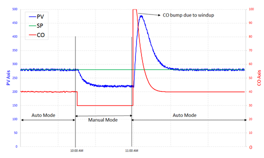
Manual to auto transfer with bump due to CO wind-up.
The remedy here is quite straightforward. The control logic should be designed to 1) Inform the PID controller when the loop has been placed in Manual mode, and 2) Have the PID controller track the value of the control valve position that is being established by the plant operator. By having the PID controller track the actual valve position, we will prevent it from winding up to either the completely Closed or Open position. So we’re done right? Well not quite.
Proportional Bump at the Time of Transfer from Manual to Auto
Assuming that we did our job and properly designed a PID tracking system that prevented the PID controller from “winding up” when the control loop was in Manual. So let’s take a look at what could happen in our previous example:
At 10:00 a.m. the operator places a temperature control loop in Manual. As before, the SP = 280°F at the time of this transition. The operator decides to manually decrease the control valve position from 40% to 30%. The PV, after several minutes, settles out at 220°F. At 11:00 a.m. the operator decides to switch the loop back in Automatic mode. At that time the SP = 280°F and the PV = 220°F. As soon as the operator flips the switch the control valve goes to 50% open (from 30%). Alarms may still trigger and disturbances to the process may still occur. Maybe not quite as bad as without tracking, but still very disruptive. What happened?
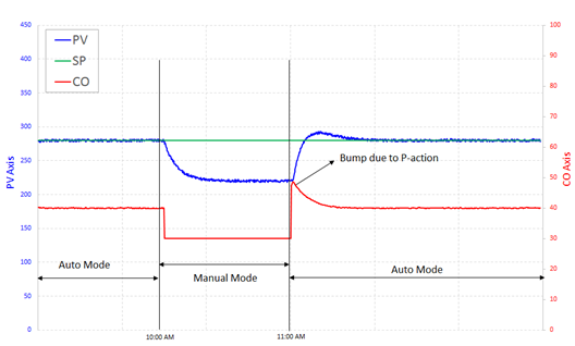
Manual to auto transfer with bump due to P-action.
Note in the above example that at the time that the switch from Manual to Automatic occurred there was an Error present (SP-PV; 280°F -220°F = 60 °F). So even though we had the PID Controller tracking the position of the Control Valve the first time it calculated a control valve position the Proportional Term of the PID controller would “bump” due to the presence of the Error. The positive aspect is that the “bump” was less than that which occurred without PID Tracking; but there was a substantial “bump” nonetheless. So now what should we do? Well there are two options:
- Design the SP to track the PV when the control loop is placed in Manual.
Most modern control systems today will give you the option to have the SP track the PV when the control loop is placed in Manual.Pros: Since the SP tracks the PV when in Manual the value of the Error at the time the operator “flips the switch” will be zero. As such there will be no “proportional bump” at the time of the switch.Cons: Operators will have to “remember” what the normal SP should be for the control loop when it is returned to Automatic mode. By having the SP track the PV the operator no longer has the SP pegged at its normal value. There could still be a bump due to P action if large change in SP is made after transferring to Auto mode.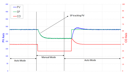
Option 1 – Bumpless Transfer by SP tracking PV
- Suppress the Proportional Action at the instant that the switch from Manual to Auto is made.
Some modern control systems provide the option of “suppressing” the Proportional action at the time the operator “flips” the switch from Manual to Automatic.Pros: The SP remains at its nominal value during the period of time that the control loop is in Manual thus preventing the operator from having to remember where the SP should be during normal operations. Eliminates the Proportional Bump.Cons: If there is an Error present at the time the operator “flips the switch” it may take a considerable amount of time to “drive the PV to the SP” since the proportional action of the PID controller has been suppressed.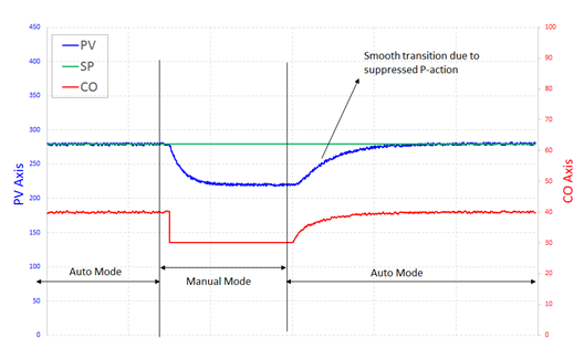
Bumpless transfer by suppressed P-action
Optimal Solution
The best method of providing bumpless transfer is dependent on a variety of factors, the most important of which is the process itself. The optimal solution is to have your PID controllers tuned so well that the operators never feel the need to place the control loops in Manual due to improper tuning. And the most cost-effective way to ensure this is by tuning your loops with ControlSoft’s INTUNE PID tuning tools software.
We can help you keep your loops in Automatic nearly 100% of the time for safe, reliable and consistent operation of your processes.

